May 22, 2020
Welding symbols and drawings are essential for learning and understanding the correct way of welding. In the case of fillet welding, the drawings and symbols and their correct interpretations are critical to learning the basics of fillet welding. Your correct interpretations of these drawings and symbols can make it convenient for you to control the welding of joints and master fillet welding.
Fillet welds are widely used in various industries that include those which produce pressure vessels and boilers. The right triangle positions itself on the reference line along with the perpendicular leg that is always placed on the left. It is the symbol of the fillet weld. You will see the dimension that specifies the fillet weld’s leg size. This dimension is often seen on the fillet weld symbol’s left side. It is also seen on the reference line’s the same side.
The equal-leg fillet welds are often used in many cases of fillet welding because the equal leg fillet welds have better load carrying capacity/pound of fillet weld. However, in some cases wherein there are some geometric restrictions, you should use the unequal-leg fillet welds. In such a case, the symbol used shows both leg dimensions that are separated or divided by a multiplication sign. These added symbols are then positioned to the fillet weld symbol’s left side. The weld orientation is also shown on this symbol, while the leg dimensions’ order is not that significant.
What Is Fillet Welding?
Fillet welding is characterized by the joining of two metal pieces together. This joining of two pieces can either be at an angle or perpendicular. The other term for Fillet Welding is “Tee Joint,” when it includes two pieces of metals that are perpendicular to one another. It is, however, referred to as lap joints when two metal pieces are overlapping with each other, and you weld at their edges.
The appearance of the weld is triangular. However, You need to consider the welder’s techniques too, as it may also have a concave, flat, or convex surface. Moreover, you can use fillet welding when connecting pipes and flanges. It is also used with the cross-section welding of infrastructure. Plus, it is used to further strengthen bolt fastenings of metal. Fillet weld is also subdivided into two types, namely: parallel fillet weld, and traverse fillet weld.
5 Parts of the Fillet Weld
If you will look at the graphical symbol of a fillet weld, you will see that there are five elements or parts to a fillet weld. These elements include the throat, leg, face, toe, and root. The deepest penetration of weld is called the root. The root is at the hypotenuse’s opposite angle. The toes, on the other hand, refer to the edges or the hypotenuse points.
However, the face is the hypotenuse or the outer visual that you would see once you look at the weld. The weld’s size is the leg length, while the face-root distance is the throat. When you do fillet welding, you should ensure that the throat is of the same thickness as the metal that you are welding.
How Does Fillet Welding Work?
The fillet welds are very applicable to heavy industries involving heavy welding machinery, buildings, ships, intricate angles, and extensive frameworks. In these industries, joints that span kilometers long are welded to create huge structures. Fillet welds are very much applicable in welding and joining corners, lap joints, and Ts joints. This is because fillet welds are more economical compared to groove welds. Moreover, fillet welds are more straightforward to prepare relative to fit-up and edge preparation.
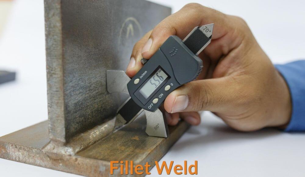
Inspecting the fillet weld legs is critical to the level of distortion and the costs of the welding process. Moreover, you can determine the fillet weld’s strength by the computed effective area of the weld of the theoretical throat or by the design throat thickness and the length of the effective weld. The formula is T x W.
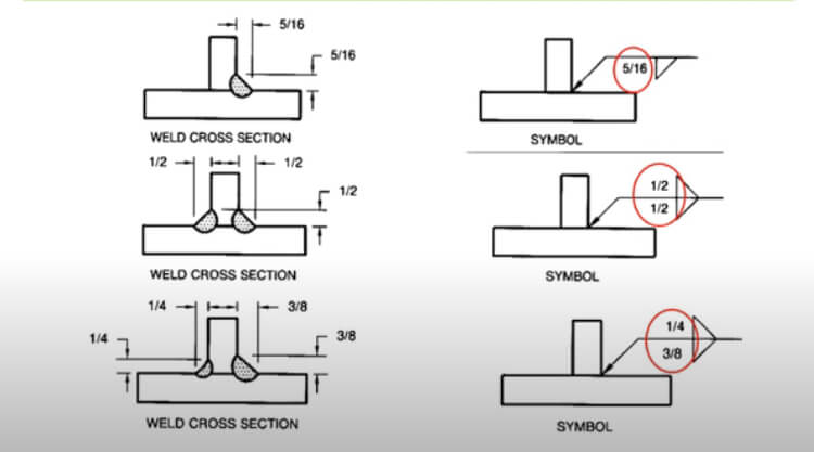
The fillet weld sizes are usually determined by the fillet weld legs. So, to determine the fillet weld sizes, you should measure the length of the fillet weld legs of the widest right triangle that you can see in the cross-section of the fillet weld.
You can then determine the theoretical throat, likewise, by the fillet weld sizes. The computation of the theoretical throat may be a bit complicated for the uninitiated to mathematics. Yet, the formula is quite simple to look at. It is S x cos45°=0.7S. It is necessary to keep the fillet weld sizes large enough so that it can bear the applied load. Yet, the specified weld size must not be too large to avoid and lessen costs and welding distortion.
Based on the Structural Welding Code (steel), the minimum size of fillet weld for every base metal thickness will specify the maximum level of convexity. This specification is crucial because if there is too much convexity, the load or stress may tilt towards the fillet weld’s toes. In such a case, it may lead to early joint failure. Strict quality should govern fillet welding. Moreover, the quality controller should carefully measure the size of the throat, concavity, convexity using different kinds of welding gauges.
Fillet Welds vs. Groove-type Welds: Which is Better?
The groove-type weld is a type of weld wherein you bevel together the parent metals forming a weld joint. Then, you enable the filler wire to flow within the grooves. However, fillet welds don’t always fully extend along the joint length. The welder usually creates a weld that is less than the joint’s length based on the specified length dimensions of the fillet weld.
Of course, the location of the fillet weld is crucial to the strength and durability of the weld. Thus, dimension lines, detailing, and hatching are required. If you see the length dimension is omitted in the symbol, then it means that you should make the fillet weld throughout the length of the joint.
Fillet welds come in intermittent forms in contrast to that of the groove welds. Intermittent, of course, means there is a gap in between each weld, or rather the welds are segmented. However, the dimension of each segment of the weld is indicated on the right side of the symbol for the fillet weld. The hyphen and the pitch dimension also come after the length dimension of the segment. The distance between the center point of each segmented weld is called the “pitch dimension.”
The intermittent fillet welds are more often indicated on the joint’s both sides by drawing a symbol of fillet weld above and below the reference line. If the segmented fillet welds are positioned opposite the joint, they are called “chain Intermittent” fillet welds. If the staggering of the segments of the fillet welds is wrought with symmetry on the joint’s both sides, then the indicators are offset from left to right of the reference line.
The American Standard, of course, carries provisions on how the contours of the fillet welds should be done, including the method on how to produce the shapes of the fillet welds. On the other hand, there is no provision on how the groove welds should be done. The shops engaged in groove weld more often are the ones that determine the specifications of the groove welds.
How To Read Fillet Weld Symbols and Notations
The fillet welding notations are valuable for fabricators. This is because the notations provide the fabricators with the basis of how the fillet welding should be wrought. If you would look at the symbol of a fillet weld, you will notice that it is in the shape of a triangle. You will also see the triangle either above or below the line of reference. The triangle is situated on one side. This side, of course, is important because it indicates the point wherein the weld and the joint will intersect.
The ISO 2553 describes the two approaches on how to designate the other side and the arrow side. These two systems include the A-system that is more often used in Europe and the B-System, which is commonly used in the United States.
The A-System is characterized by two parallel lines representing the reference line—one of which is a segmented line, and the other one is a continuous line. The B-System, on the other hand, comes with a single continuous reference line. The weld will be on the arrow side if there is only one line, and the triangle is placed below that of the reference line. However, if the triangle is set above the reference line, the arrow’s opposite side has the triangle.
If an arrow points to a joint and contains two triangles—one of which is above the line and is even with the other, you should make a fillet weld on both sides of the joints. However, you will find a small circle around the point where the arrow and the reference line are connected. If such is the notation, then, the weld should be continuous around the metal with a square or pipe shape. You will also find in the notation the strength of the weld. The strength is usually indicated by a number or letter combination positioned prior to the flat line.
A perfect example would be “E70.” This means that the tensile strength of the arc electrode should be around 79,000 pounds-force/square inch. You will also find symbols indicative of the required aesthetics of a particular weld. An example of which would be a curve that veers away from the hypotenuse. Such a symbol means that you need to do a concave weld.
If you are required to make a flat-faced weld, you will see a straight line parallel to that of the hypotenuse. On the other hand, if you see a curve pointed toward the hypotenuse, you need a convex weld.
You can manipulate the weld’s surface by employing various welding techniques. You can also manipulate the weld by using grinding tools. Manufacturers will also sometimes indicate the leg’s measurements and the weld’s length. They may also indicate the measurements of the weld’s spacing.
You will sometimes find measurements like 1/8″ x 3/8″ to the triangle’s left. The 1/8″ would refer to the weld’s vertical leg. The horizontal leg, on the other hand, is 3/8.” On the left side, however, you may also find the length of the weld.